The Role of Rubber Components in High Speed Automated Production Lines
The combination of grip, repetition, motion direction and material uniformity plays a crucial role in the performance of fast automated devices
Sudden changes in high-speed automation get turned into frequent occurrences. Just one in ten thousand cycles of picking by a suction cup would probably still be enough to stop the line at several occasions during a single shift. Similarly, the soft stop that is too slow to recover might cause the change in position of part that is about to be inspected or manipulated before the camera or tool can reach it。
Rubber elements at the interfaces of automated production lines are the ones that do these actions because they can also hold tight together, be flexible, reduce vibration, and come back to their original shape.
Their effectiveness relies merely on the conditions that do not go beyond a defined level of heat, wear and production deviation.
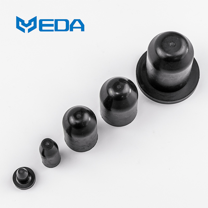
Lifting at a faster pace changes the way a product is designed
If a component works well during installation under slow conditions that does not necessarily mean it will work at production speed. For instance, fast acceleration could cause the suction lip to detach from the product. A seal may get hotter. Bumpers might be still bouncing back when impacts again arrive. Therefore, speed changes the loading rate and cycle count.
Hence, it is very important to specify rubber parts in high-spped automation with parameters like cycle time, acceleration and dwell. Maximum machine speed alone is not sufficient. There are circumstances when the part might face the most extreme stress: for example during an emergency stop, a quick change of direction or a brief contact at the end of the travelling route.
According to the International Federation of Robotics, in 2025 global industrial robot installations amount to 603,000 units. This figure shows that the number of robots in operation worldwide has exceeded five million. As a result, robot-handled automated systems require reliable and flexible robot-to-robot interfaces that will help in line availability.
Grippers should stay reliable when the product varies
Rubber vacuum suction cups for automation are able to follow the shape of the work piece and at the same time form the perimeter that is required for holding items through vacuum. The shape of the lip, the size of the cup, the design inside the bellows, the degree of hardness of the material, and the condition of the surface all contribute to sealing performance. A sealed vacuum requires a different type of cup performance depending on the substrate - a smooth metal plate, a porous cardboard box, and a flexible pouch will each need very different features.
The static lifting force is only a reference point. During a faster speed movement, the inertia can shift either the object itself or cause the sealing lip to lift off the holding surface. The testing of the suction mechanism should incorporate the planned acceleration, robot posture, the product center of gravity, and any oil, powder or moisture on the surface.
A Schmalz case describes a robot cell that handles semiconductor components using 176 flat suction cups made from NBR-ESD. The supplier reports a target rate of up to 31,000 chips per hour. Small axial movement and electrostatic-discharge control were important because the parts were sensitive and had to be placed precisely.
Piab published another case involving packaged snacks on a FlexPicker robot. Worn cups had caused loss of vacuum and dropped products. The supplier reports that a different rectangular cup and vacuum arrangement improved robot productivity by 70 percent by reducing drops.
These are public supplier cases, not Yida customer results. They show why rubber suction cups for automation must be matched to surface, motion and vacuum design. The reported figures cannot be transferred to another line without its own trials.
Repeated Motion Exposes Weak Geometry
Flexible seals, bellows, diaphragms and cable grommets can move millions of times in an automated cell. Cracks often start where strain concentrates: a sharp thickness transition, fold root, trimmed edge or clamp boundary. A strong compound cannot correct a shape that forces one small area to carry most of the movement.
Stroke and speed should be recorded separately. A short stroke at very high frequency can generate heat and fatigue, while a long occasional stroke may create greater peak strain. Angular offset and torsion also need to be stated when the movement is not purely linear.
Custom rubber components can integrate mounting beads, lips or strain-relief sections, reducing separate pieces on the assembly. Integration also makes molded dimensions part of the motion. Tooling, wall thickness and clamping must hold the flexible zone in the intended location.
Vibration Can Penetrate the Product and the Sensor
Vibration isolation with rubber layers may be incorporated beneath the ground, the driver and frame connection, or close to a camera and end-effector. Depending on the location, each one has a particular aim. To achieve the purpose, he may reduce the transmission of floor vibrations, prevent image blur, or shield the load cell from tool shock by various means.
A more compliance may also allow an unexpected deformation A gentle mount may prolong the settling of the move and lower the positioning rigidity. The effectiveness of isolation should be judged from the frequencies of the forced vibration by the machine, the mass it holds, and how much displacement is tolerable, rather than hardness only.
In order to carry out rubber vibration isolation on a high-speed production line, the measurements should include all startup periods, regular running, speed changes, and emergency stopping situations. A component that shows excellent performance at a single, unvarying frequency may encounter a less desirable condition as the machine continues to gain speed.
Stoppers and Shock Absorbers Take a While Before They Are Ready to Work
In many cases, rubber stoppers are molded to be bumpers, protecting slides, gates, pallets, and parts from the end of the motion. The force they exert increases when they are compressed; internal hysteresis, on the other hand, dissipates some of the motion energy into heat. After numerous collisions, the temperature may rise significantly, modifying the behavior of the part without the part reverting to its original form.
Energy, the speed at which the objects approach each other, the deflection potential, and how often such events occur are the inputs that should be used correctly.
In a bumper that is chosen based solely on the maximum static load it bears, it is highly possible that the bumper reaches solid compression and thus the load peak that it is able to transmit gets very high in magnitude.
In addition, if contact is off the center, an insert can be bent or the rubber can be cut in a shear action at both points of the contact.
Seals Should Limit Friction and Prevent Contamination
Dynamic seals in pneumatic cylinders, indexing units, dispensers, etc., have to control the leakage to its lowest degree without creating significant breakaway force.
Very frequent cycling of a sealing system may lead to lubricant consumption and the contact surface becoming polished, which in turn results in the accumulation of heat. Moreover, if a tiny particle is trapped into the seal it may become a major source of abrasion that can cause the wear with every stroke.
Components working under very high speeds have to tolerate the harsh chemicals such as cleaning agents, process oils, dusts, or food residues. In general, the resistance to the different chemicals varies greatly with the type of material and thus, one must decide based on the real formulation of the material that was used plus the actual exposure conditions.
Potentially, a seal utilized on a food, battery, or semiconductor line may have to follow cleaning requirements not only for its mechanical properties but more importantly even if the component is still in good condition. The presence of particles, extractables, marking, and electrostatic characteristics in the component may influence the whole process.
Production Consistency Matters More at High Throughput
A small change in lip thickness, hardness or cure may have little effect during a manual trial but alter release timing on a fast machine. The drawing should identify the dimensions and surface conditions that control grip, friction, airflow or recovery.
Custom rubber components should be sampled across cavities and production lots when variation could affect line timing. Functional checks can complement dimensional inspection. For example, a controlled vacuum-decay, deflection-force or pull-off test may reveal a change that a general visual check cannot.
What Common Standards Establish
ISO 10218-1:2025 covers industrial robot safety, while ISO 10218-2:2025 addresses robot applications and cells. They do not qualify the fatigue life of an arbitrary cup, seal, bumper or mount.
ASTM D430 provides comparative dynamic-fatigue tests for rubber and rubber-fabric materials. The standard states that no exact correlation with service is implied because service conditions vary. A coupon test does not reproduce the molded geometry, preload and temperature of the line.
ASTM D471 evaluates changes after controlled liquid exposure, and ASTM D575 measures compressive behavior. They can help compare materials, but neither demonstrates cycle reliability, gripping performance or machine accuracy for rubber components in automated production lines.
A Finished Part Validation Sequence
Begin with material identity, dimensions and visual condition. Inspect sealing edges, flexible walls, bonded inserts and trimmed areas. Assemble parts with production tools on mating hardware at the relevant tolerance limits.
Run a slow functional check to confirm fit and basic operation, then increase to the intended production speed. Measure the quantity linked to the part's job: vacuum leakage, pick success, friction, displacement, impact force, vibration or cycle time.
Add the specified temperature, contamination, chemical and cleaning conditions. Use representative products, because surface variation can dominate gripping results. Include planned stops and restarts when the part cools or relaxes during idle periods.
Continue for a cycle count connected to the proposed maintenance interval. Recheck the initial measurements at planned stages. After testing, inspect cracks, wear, permanent deformation, bond movement and any transfer of residue to the product or machine.
Define acceptance limits before the trial. A statement such as no failure is too vague for a fast line. The plan should identify allowable missed picks, leakage, force change, vibration, dimensional drift and visible damage.
Information Needed Before Development
Provide cycle time, speed, acceleration, stroke, impact conditions and annual cycles. Add the product surface, vacuum level, pressure, load, temperature, chemicals, cleaning process, lubrication and available mounting space.
State the functional limit and the consequence of failure. Useful details include allowable missed-pick rate, release time, leakage, settling time, product marking and planned replacement interval. Photos or video of the motion can clarify loads that are difficult to show on a part drawing.
Working With Yida
Dalian Yida Precision Rubber Products Co., Ltd. develops molded elastomer parts for customer-defined equipment. Our review can cover moldability, compound options, critical geometry and inspection features for parts used in automated handling, sealing, damping and protection.
The most useful starting point is the line condition rather than a generic material request. When speed, motion, environment and acceptance data are available, Yida can support a sample plan for high speed automation rubber parts without treating a standard material test as proof of finished-line performance.