Custom Rubber Piston Seals for Hydraulic and Pneumatic Systems
The factors pressure direction, speed, surface finish and lubrication play a role in finding out the proper design for a piston seal.
A piston seal prevents pressure from passing between opposite sides of a piston that moves. This is a very simple statement. Actually there are several factors that are in contradiction which a seal has to handle. It is necessary for the seal to prevent leakage inside as much as possible while moving at a frictional level that is acceptable. Furthermore, it has to stand varying surface conditions and withstand the repeated reversals of direction and in the same time it should neither have its groove left nor it should be rolled.
Special rubber piston seals are used when none of the standard profiles suit the groove, the material of the hole, the working fluid, speed or the assembly procedure. Best seal profile has to be decided considering the whole cylinder. Material data sheets can not reflect how a particular rubber seal would work in the user's bore.
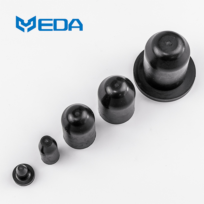
Pressure Direction Determines the Basic Profile
A single-sided seal is mostly energized from one side. A double-acting cylinder requires control in both directions which may mean the use of a symmetrical profile or sealing elements pair. The pressure change could unload one lip and load the other quite quickly.
Frequently, hydraulic piston seals come into play where high pressure with fluids that can't be compressed is the norm. Clearance together with pressure peaks tend to push rubber towards an extrusion gap. Depending on design, a harder compound may be needed or a support ring or profile that limits material movement at the edge.
In the case of pneumatic piston seals, they tend to work on the level of lower pressure but can cycle rapidly with lubrication being minimal. The breakaway force in a dry state, along with retaining the lubricant, may turn out to be more significant than the maximum pressure capacity. Dry air, condensed water and practices of the maintainer will also affect wear.
Groove and Bore Make Sealing Interface
Groove and bore, on the one side, make a sealing face; on the other side of it they are the means of mounting. A bore surface has to be such that it does not cut the lips of the sealing element and at the same time supports a stable film of oil or grease there. Very rough surface can increase wear and leakage quite quickly. A very smooth surface, though, may still contain directional traces of machining like scratches or small peaks that can be very damaging to the sealing element.
Parker's design advice for piston reciprocating sealing is that contact-surface finish, groove finish and lead-in chamfer are individual features to pay attention to.
This lead-in chamfer helps to protect the sealing edge at the time of assembly.
Rounded, clean transitions reduce the risk of cutting or twisting the seal.
Paper sealing is also influenced by the extrusion space formed by the piston, the bore and the bearings. Load on the side can make larger one side gap. Wear rings or guides could be necessary to the piston stay centered and also the seal not to be loaded for mechanical guiding.
Friction Variation Throughout The Motion
First motion can require more force than continuous sliding.
The difference mentioned may result in low speed stick- slip which in turn, will have a bearing on position. Lip seal compression load, surfaces, lubrication, pressure and materials are the main factors affecting this phenomenon, so it should be friction that is measured in the intended application.
At higher pressure, a seal which works well with respect to friction at low pressure may behave differently. Hence, custom rubber piston seals need to be tested against pressure and temperature extremes as well as speed and not just a typical set of conditions.
A Public Fluid Power Example
Parker presents a C2 compact U-cup profile suitable for hydraulic and pneumatic cylinders. The technical data sheet provides varied range of pressure levels for the two technologies and also points out the max values depend on cross-section and compound. A piece of good advice, too, it states is to keep the surfaces free from sharp edges while putting it in place.
This case demonstrates that a single profile is available for two mediums but the restrictions and fitting suggestions are not the same. This example is an open-source supplier example, not something Yida does. A custom-made bore, fluid, or cycle may well demand a unique solution.
Material Choice Follows Fluid and Motion
Piston seal material selection starts with the hydraulic fluid or compressed-air condition, then adds temperature, speed, pressure and wear. NBR is common with mineral oils. FKM may be considered for higher heat or aggressive fluids, while EPDM can suit selected water-based media but not petroleum oil.
Polyurethane can provide strong wear and extrusion resistance, though low-temperature flexibility, hydrolysis and fluid compatibility depend on grade. Rubber profiles may offer different friction and resilience. The family name does not replace compound-level data.
Piston seal material selection should include the assembly lubricant. A grease that simplifies installation can swell the lip or change breakaway behavior after storage. Cleaning agents and fluid additives also deserve review when contact is possible.
Catalog Limits Are Not Simultaneous Ratings
Trelleborg's hydraulic seal catalog states that listed maximum pressure, speed and temperature values cannot necessarily be used at the same time. This is an important design rule. Heat generated by speed can reduce the material margin available for pressure and fluid exposure.
ISO 7986 provides standard test methods for seals used in oil-hydraulic reciprocating applications. It supports comparable testing, but a standard test condition does not cover every bore surface, contamination level, side load or duty cycle.
ASTM D471 can compare changes after liquid exposure, and ASTM D412 can measure tensile properties. Neither method proves the leakage or wear of hydraulic piston seals inside a working cylinder.
A Finished Seal Test Sequence
Inspect dimensions, lip condition, flash and molding defects before assembly. Confirm groove width, bore diameter, lead-in and surface requirements at tolerance limits. Record the installation method and reject tools or edges that can scratch the sealing surface.
Measure breakaway and running force at the required pressures and speeds. For pneumatic piston seals, include oiled and specified low-lubrication conditions when relevant. For hydraulic designs, include pressure reversals, dwell and justified peak events.
Record internal leakage across the operating range. Cycle the cylinder at representative stroke, frequency, temperature and side load. Add contamination only when the test can reproduce the intended environment safely and consistently.
After cycling, repeat leakage and friction measurements. Inspect lip polishing, cuts, extrusion, rolling and permanent deformation. Dynamic cylinder sealing should pass functional criteria agreed before the test, not merely look acceptable after disassembly.
Application Details Needed Before Tooling
Provide bore and groove drawings, pressure direction, fluid, temperature, stroke, speed, cycle rate and expected life. Add the extrusion gap, side load, surface specification, lubricant, assembly route and allowable leakage and friction.
Dalian Yida Precision Rubber Products Co., Ltd. develops molded elastomer components for customer-defined applications. Yida can review manufacturability, compound options, lip geometry and critical dimensions for hydraulic and pneumatic sealing projects.
In order to provide a dependable piston seal a designer should match the profile to the cylinder and then the seal will go through a motion that is representative for it to be able to resist. That method can give a better result than just picking the ones that look good by pressure or hardness.